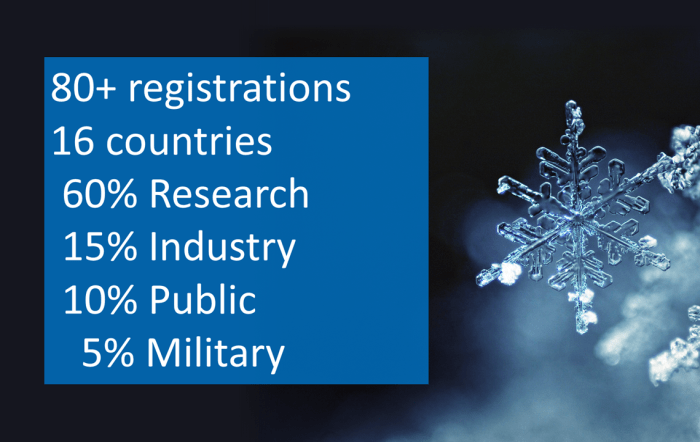
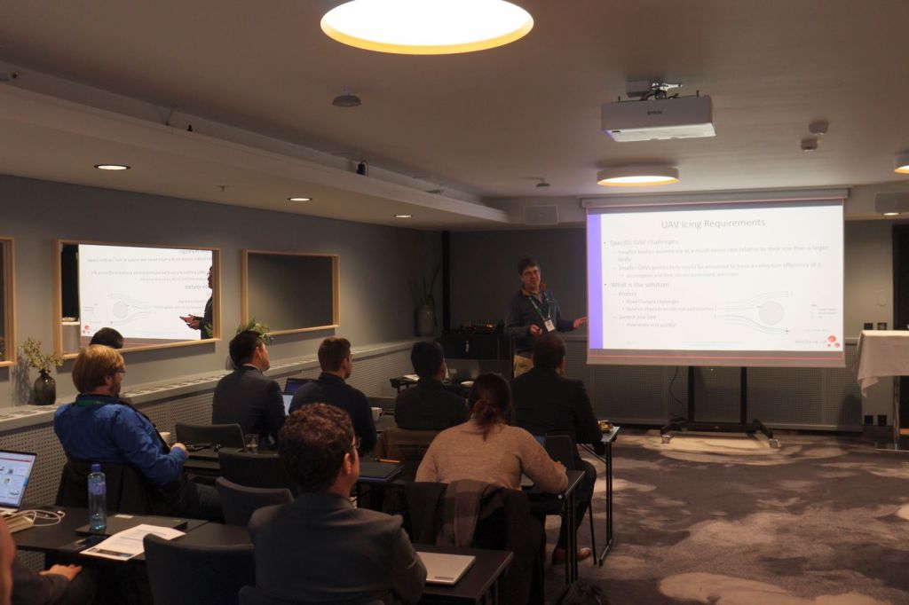
One week after the 1st UAV Icing Workshop in Trondheim, we thank all participants for joining! With your support, we have made this event into a successful forum for discussing UAV icing-related challenges in research, industry, and regulations. More than 80 participants were registered for the event with about half of them physically present in Trondheim. We had representatives from 16 countries, spanning all around the globe. Many European countries, but also Canada, USA, South Korea, China, and New Zealand – resulting in the working being a truly international forum! Furthermore, about 60% of the participants had a background in research, 15% in industry, 10% in government, and 5% in defense.
We are happy to announce that the UAV Icing Workshop will return again in 2024! More information will follow on: www.uavicingworkshop.com.
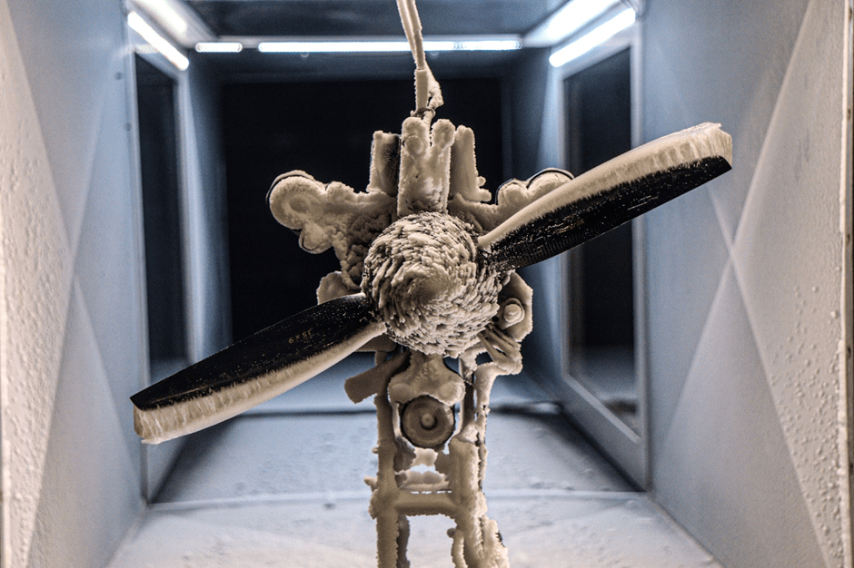
**NEW PUBLICATION** When flying in icing conditions, uncrewed aerial vehicles (UAVs) face severe dangers. The propeller of the UAV, which is creating the thrust for the UAV is especially sensitive to the accumulation of ice during flight in atmospheric icing conditions. To estimate the impact of icing on the propeller, we conducted experimental tests in an icing wind tunnel. The icing wind tunnel is a special facility whose main feature is a spray system, that can emulate the conditions in a cloud. The propeller was mounted on a test-bench that recorded the forces on the propeller. Also, a high-speed camera captured images of the ice on the propeller to get further details on the ice accumulation process. The propeller was tested across a wide range of icing conditions to separate the different influence factors on the icing on the propeller.
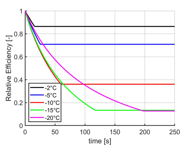
Performance of the propeller in icing conditions. Efficiency and vibration levels displayed.
The ice shapes start to grow on the leading edge of the propeller. This ice shape disturbs the airflow around the propeller. The disturbed airflow makes the propeller less efficient. If the propeller is no longer producing enough thrust, the UAV will no longer be able to continue to fly.
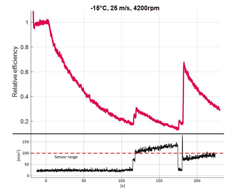
If the mass of the accumulated ice has grown to a critical points, parts of the ice will break off and thrown away from the propeller. The removal of ice improves the aerodynamic performance of the propeller in the briefly, until the ice has been formed again. But the blocks of ice breaking are also a risk to the UAV. The ice fragments can hit other parts of the UAV, like the empennage. More importantly, the ice shedding leads to an imbalanced mass between the propeller blades. This leads to very strong vibrations. In our testing campaign those vibrations exceeded the 10G measurement rage of the used sensor. This is the reason why focusing on the ice shedding process is very important to understand the risk of ice on the propeller of a UAV.
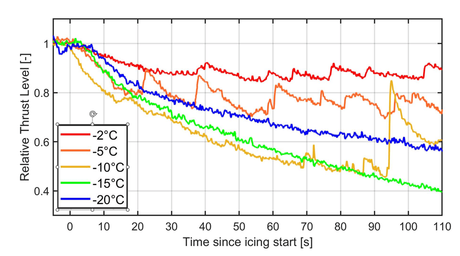
The analysis of the ice shedding has shown that the amount of ice that can form on the propeller is strongly dependent on the temperature. Lower temperatures lead to larger amounts of ice on the propeller, while at higher temperatures the amount of ice on the propeller is lower. The size of ice fragments that shed from the propeller were the largest at temperatures of -10 °C.
Propeller performance at different temperatures.
Another focus of the study was the aerodynamic performance of the propeller with ice accumulated on the propeller. Ice on the propeller reduces the thrust of the propeller and its efficiency. This could be measured by our test setup to see how different temperatures influence the propeller. Here it is clear that the loss in performance is the worst for temperatures of about -10°C. This hits a sweet spot between higher temperatures which have less amount of ice freezing on the propeller and lower temperatures where the ice shapes on the propeller are very streamlined and do not influence the performance of the propeller as much.
Predicted Performance of the propeller in icing conditions.
The whole range of measurements has been taken and merged into an algorithm to predict the performance of the propeller across a range of conditions. This can be used as a tool in flight simulators to predict the influence icing has on the flight of a UAV. This enabled the development of advanced path planning methods to optimize flight routes to reduce the impact of icing and to train autopilots to cope with icing on propellers.
**NEW PUBLICATION** Aircraft without ice protection systems will face severe issues when flying in icing conditions. To reduce the risk of losing the aircraft, the aircraft must either remain grounded when the risk of icing exists, or it must be equipped with an ice protection system. As of today, no mature ice protection system exists for small unmanned aircraft. To fill this gap, a new ice protection system was developed and thoroughly tested in an icing wind tunnel.
The occurrence of in-flight icing can significantly influence the performance of aircraft. Hence, every aircraft that is supposed to fly in or through icing conditions must have an ice protection system (a system that protects the aircraft from the adverse consequences of icing). This can be particularly important for unmanned aircraft. Drones, uncrewed aerial vehicles (UAVs), unmanned aerial systems (UAS), and urban air mobility (UAM) are often used as synonyms to describe unmanned aircraft – an area that is getting more and more popular.
Unmanned aircraft are typically more prone to icing than manned aircraft. Hence, ice protection systems are extremely important for unmanned aircraft to allow operation in all weather conditions. However, as of today, unmanned aircraft are not commercially available with an ice protection system. This means that unmanned aircraft will typically remain grounded when potential icing conditions are present (liquid droplets are in the air at temperatures below the freezing point).
An important parameter for the quality of an ice protection system for unmanned aircraft is the energy-efficiency. The more energy the ice protection system requires, the less the aircraft’s possible range. Since the available energy on board the aircraft is significantly lower for unmanned aircraft than for manned aircraft, this is a bigger issue for unmanned aircraft than for manned aircraft.
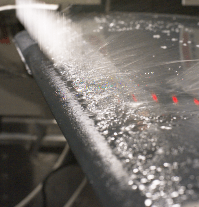
An example of a possible ice protection system for unmanned aircraft is D•ICE. D•ICE was originally developed at the Norwegian University of Science and Technology (NTNU) and is now commercially developed by UBIQ Aerospace. It is an electrothermal system that is designed to work best in de-icing mode. This means that after some time of ice accretion, the wing is heated by powering carbon fiber layers inside the wing. The heat melts some ice at the interface between the wing and the ice. When enough ice is melted, the ice will shed from the wing, as can be seen in the picture below.
Ice sheds from the wing after the heating zones have been activated.
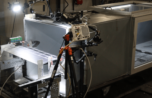
To examine the performance of different settings of the ice protection system, tests were performed in the icing wind tunnel at the Technical Research Centre of Finland (VTT). An icing wind tunnel is a special wind tunnel that is equipped with a spray system and can be operated at constant temperatures below freezing. The wing was placed in the airstream that contains water droplets. After allowing ice to accumulate on the wing for four minutes, the heating zones are activated, and the de-icing procedure starts.
The wing is mounted inside the icing wind tunnel facility.
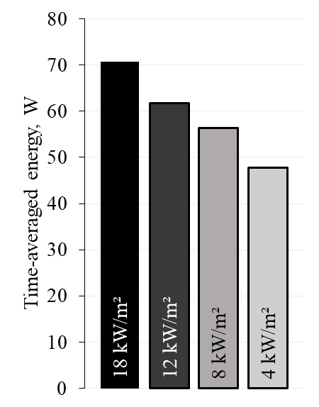
One of the key findings was that the heat flux provided to the heating zones is one of the operational settings of an electrothermal ice protection system that can be adjusted. Increasing the heat flux results in higher temperatures at the wing’s surface; hence, the ice starts melting faster. As a result, ice shedding happens faster when higher heat fluxes are used. While one might think that faster shedding also results in a more energy-efficient de-icing process, this is not always true. On the contrary, the results showed that – averaged over time – more energy was required for the de-icing when higher heat fluxes are used.
The heat flux provided to the heating zones is one of the operational settings of an electrothermal ice protection system that can be adjusted. Increasing the heat flux results in higher temperatures at the wing’s surface; hence, the ice starts melting faster. As a result, ice shedding happens faster when higher heat fluxes are used. While one might think that faster shedding also results in a more energy-efficient de-icing process, this is not always true. On the contrary, the results showed that – averaged over time – more energy was required for the de-icing when higher heat fluxes are used.
The time until shedding happens is reduced for higher heat fluxes.
The energy that must be used to de-ice the wing is lower for lower heat fluxes.
This means that for an encounter with a given duration, using lower heat fluxes for de-icing results in less energy used although the individual ice shedding times are faster.
While it should be said that the results might be different for different geometries and internal structures of ice protection systems, the study showed some potential ways to reduce the energy needs of ice protection systems. Using the results of the study to improve ice protection system operation modes will hopefully enable the flight of unmanned aircraft in icing conditions soon.
**NEW Publication** Icing severity indices are a measure for the in-flight icing risk and are an important factor for path and mission planning. Small aircraft, such as unmanned aerial vehicles (UAV) and urban air mobility (UAM) vehicles, are particularly sensitive to icing and thus proper assessment of weather risks is critical.
Icing severity is a metric for how quickly in-flight icing degrades the performance of the aircraft in a certain area. Performance means the ability of the aircraft to generate lift and sufficient thrust to stay airborne. In icing conditions, lift generation of the wings decreases while drag increases and thrust of the propeller decreases. This ice accumulation is very dangerous and is likely to lead the UAV to crash. For these UAVs, knowing the icing severity in an area becomes crucial, as they are much more sensitive to icing compared to their larger manned counterparts. Hence, having an accurate index is vital for planning purposes as to minimize hazardous conditions and to enable increased mission success rates.
Comparison between unmanned and manned aircraft with 6 mm of accumulated ice
Our recently published article proposes a new method to calculate an icing index that is better suited for unmanned aircraft. Icing indices today – as defined by the Aviation Weather Center (AWC) – categorize icing severity levels according to how fast 6 mm of ice accumulates on an airfoil. The issue is that this fixed value of ice thickness will have different degrees of impact, depending on the size of the aircraft. The amount of ice build-up that is deemed severe is relative to the size of the aircraft. One can think of it in terms of ice relative to the airfoil size, and the larger the fraction the worse it is. A small aircraft will experience severe icing effects with 6 mm, while a larger aircraft it might experience just light icing effects. The AWC icing index also does not account for the type of ice encountered which has been shown to degrade performance differently. Hence, the AWC definition is lacking in scalability and does not differentiate between different meteorological icing conditions. Our new proposed method compensates these shortcomings.
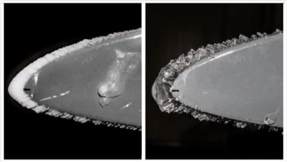
Different ice types. Rime ice to the left, glaze ice to the right.
There are two main types of ice that are of interest, rime ice which preserves the airfoil shape, and glaze ice which leads to more uneven surfaces leading to worse performance in general. One more aspect of ice types is that it affects different aircraft surfaces differently. Rime ice is less severe on the wings while glaze is worse. On the propeller, it is the opposite. The main reason is that the propeller can shed ice due to rotational forces. Glaze ice has little effect on the propellers as it can shed this ice type completely. Rime ice has a higher adhesion force which allows it to hold on more. It can also lead to uneven shedding as rime ice has less cohesion with itself which leads to increased degradation.
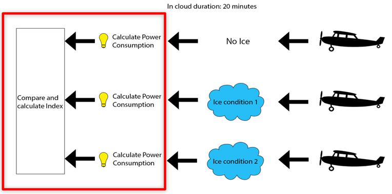
Proposed method and assumptions made. It is assumed that the aircraft undergoes twenty minutes of icing before extracting performance metrics in the form of lift and drag curves. These lift and drag curves are then used directly to compare power consumption to yield the index. The aircraft are exposed to different icing conditions to yield different performance curves for comparison. Here icing condition 1 might be a condition for glaze ice, while ice condition 2 is for rime ice.
Our proposed method assumes exposing an aircraft to different ice for 20 minutes, then uses lift and drag curves to calculate the performance degradation directly. The increase in power consumption is compared to the baseline no ice condition to calculate the index. By calculating the index this way, scalability is not an issue as the performance curves are directly linked to the aircraft and key variables, such as wingspan, are included in the calculation. The different icing conditions that are tested also consider specific icing conditions. It does mean, however, that the proposed method is aircraft specific and will require more testing in general to get the iced performance curves.
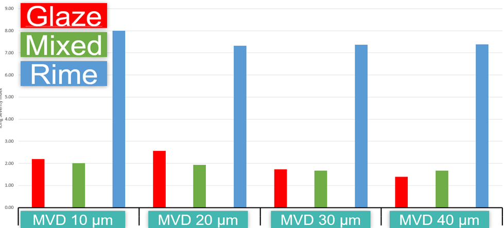
Some of the results are shown below with icing severity index values at different median volume diameters (MVDs) of droplets and it shows that rime ice is overall worst. This is because the propeller is what is keeping the aircraft in the air as it is the propeller that generates thrust and hence dominates the index. A decrease in propeller efficiency means it compensates by an increased consumption in power to deliver the same thrust. With longer icing durations, this might change because the wing does not shed ice naturally as the propeller does. Hence, with longer durations, the glaze will ultimately overtake rime as the worst ice type.
Icing severity indices for different ice types and MVD. An icing severity index of 3 means that three times as much power is consumed compared to no ice conditions. The addition of different ice types is to compare different ice conditions.
To summarize, icing indices today have been found to be inadequate for planning purposes for typical UAVs and UAMs. UAVs and UAMs tend to be much smaller than the commercial airliners and icing indices today do not take size into account. Our proposed method uses icing performance degradation metrics directly to calculate an icing index. This new method accounts for the problems with scaling and also accounts for different icing conditions. It is, however, more complex to calculate as it is aircraft specific.
To improve upon what is investigated in the paper, including 3D effects, and expanding the investigated icing conditions would be beneficial for a more accurate index.
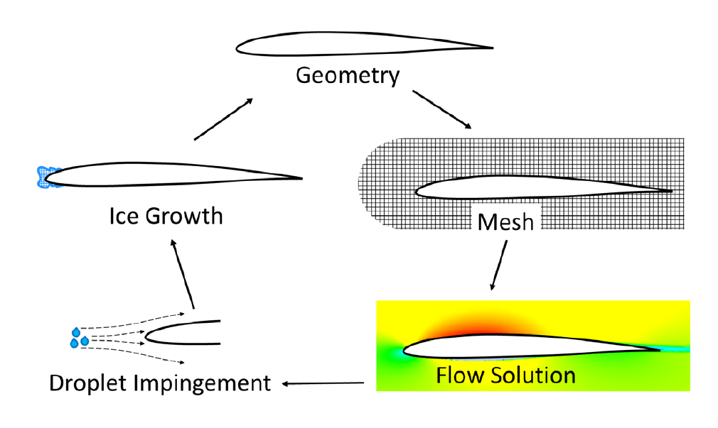
**NEW PUBLICATION** Computational fluid dynamics (CFD) simulation methods are one of the most important design and development tools for aircraft – manned or unmanned. For the challenge of in-flight icing, special icing CFD codes have been developed such as FENSAP-ICE or LEWICE3D. These tools can simulate and predict the behavior of airfoils and aircraft in icing conditions. A common characteristic of these icing CFD tools is that they have been designed for manned aircraft — typically large passenger airplanes. When it comes to unmanned aircraft — unmanned aerial vehicles (UAVs), unmanned aerial systems (UAS), drones, or urban air mobility (UAM) vehicles — the existing icing CFD codes have significant limitations.
In a recent publication, we explore these limitations and gaps. The objective is to highlight the main challenges of icing CFD on unmanned aircraft and to suggest research steps to overcome them. In short, the main challenge is related to the low Reynolds numbers at which unmanned aircraft operate. Existing icing tools often use models that are based on experiments or are validated at high Reynolds numbers at which manned aircraft operate. The application of such models is thus limited when applied to unmanned aircraft. In addition, there are several physical flow phenomena that occur more frequently at low Reynolds numbers and which have gotten little attention for manned aircraft. The main issues are the following:
Laminar-turbulent transition;
Surface roughness modeling;
Laminar separation bubbles;
Turbulence models for low Reynolds numbers;
Ice shedding model for rotors and propellers;
Electrothermal ice protection systems;
and lack of experimental validation data.
Based on the findings in the paper, we suggest the following steps to advance icing CFD on unmanned aircraft in order to unlock the full potential of digital twin development methods:
Apply advanced turbulence models in existing icing CFD codes to improve the capabilities to capture low Reynolds number flow effects. In particular, LSB, laminar-turbulent transition, and surface roughness interactions.
Generate validation datasets from experiments with conditions and geometries specifically for unmanned aircraft. Conduct validation of existing icing CFD tools for ice accretion, aerodynamic performance degradation, and ice protection systems.
Develop or adapt existing models for ice shedding, surface roughness, and ice density that are valid at low Reynolds numbers.
Flowchart of the typical simulation process for icing CFD.
Announcing the 1st international workshop on icing of unmanned aircraft. The UAV icing workshop will be held in Trondheim (Norway) and online during November 29-30, 2022. The workshop will be hosted by the UAV Icing Lab at the Norwegian University of Science and Technology (NTNU). The objective of this workshop is to provide a platform for stakeholders in science and industry to discuss the challenges and technical solutions of icing for unmanned aircraft. We highly encourage all participants to contribute with a presentation relevant to the workshop objective. Find more information about the workshop online: www.uavicingworkshop.com.
Location/travel: The workshop is held in the Scandic Nidelven hotel in Trondheim. Trondheim has an international airport with direct flights to London, Amsterdam, Olso, Stockholm, Helsinki, Copenhagen, and more. Green transportation options are available by train via Oslo.
Cost: NTNU will cover fees for the conference for up to 50 participants on a first-come-first-served basis. This includes two lunches and a dinner. Travel and accommodation costs will need to be covered by each participant. We will offer special rates for the conference hotel (Scandic Nidelven).
Registration: You can register online here: https://register.uavicingworkshop.com/. Registration for presentations closes 1st October and for participation 21st October 2022.
Written by Bogdan Løw-Hansen, PhD candidate. Today, harsh weather conditions and especially icing are a big problem for uncrewed aerial vehicles (UAVs). Several solutions exist, but many require substantial amounts of energy to operate them, which are not always available on smaller UAV platforms. To this end, the UAV Icing Lab at NTNU is currently conducting research on the optimization of an electrically heated de-icing system. The researched solution is based on an ice shedding detection algorithm presented here.
The problem with icing
Research on in-flight icing for uncrewed aerial vehicles (UAVs) is a new topic that has only recently started to gain momentum. This is driven by several factors. For example, a survey on civil applications of UAVs reports that small to mid-sized UAVs with a wingspan up to a couple of meters have significant potential to succeed in many commercial applications [1]. Other factors are based on the fact that UAVs have already been shown to be effective in critical missions such as search and rescue, human organ transport, and surveillance [2,3]. Furthermore, UAVs have been able to provide crucial capabilities in modern warfare [4]. For instance, in the ongoing conflict in Ukraine, the Ukrainian forces have been so successful at deploying their UAVs that it has led to the creation of a patriotic song about them [5]. Together, the high utility of current UAVs and the projected growth of the global UAV market, estimated to reach over $25.13 billion by 2027 [6], have opened opportunities for further funding of UAV research. One of the research topics presently receiving attention and funding is the operation of UAVs in harsh weather conditions. Among the challenging weather conditions, the icing conditions, which cause a build-up of ice on the wings of the UAV during flights, are considered to be especially problematic. In-flight icing is a critical issue to solve because it has been recognized as a severe hazard for UAVs, leading to problems ranging from reduced flight performance to complete loss of the vehicle in extreme situations [7]. Furthermore, icing conditions are relatively common phenomena, especially in cold climate regions such as northern Europe and northern America. In fact, if icing conditions weren’t a problem, the time window of when it is safe to operate a UAV could have been more than doubled in certain locations [8].
The electric ice protection system
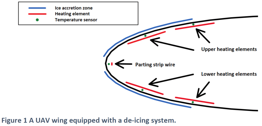
One of the developed solutions to make UAV operations in icing conditions safe is based on an electric heating system. The heating system uses power stored in batteries on board the UAV to heat the UAV wings when the vehicle is experiencing icing. This makes it difficult for the built-up ice to stick to the wings’ surface and leads to ice shedding. Figure 1 shows a schematic of such a heating system inside a UAV wing. The particular system displayed in Figure 1 is developed by UBIQ Aerospace in collaboration with the NTNU UAV Icing Lab. The IPS has four heating panels and one heating wire per wing. All of the heating elements stretch across the length of the wing. In addition, the IPS includes five temperature sensors used to measure the effectiveness of the applied heat.
Optimizing the ice protection system with an ice shedding detection algorithm
The electrically-heated IPS is used to initiate ice shedding when a critical amount of ice has been accumulated. A successful ice shedding is presented in Figure 2. The process shows a de-icing test performed in an icing wind tunnel, in which a UAV wing section is exposed to artificial icing conditions. The de-icing process can be described as follows. When enough ice has accumulated, the heating elements are used to melt some of the ice nearest to the wings’ surface. This loosens the ice, letting the incoming air shed the ice off the wings. By applying heat and shedding the ice, the IPS makes it possible to ensure that the amount of build-up ice never reaches the point where it becomes dangerous for the UAV. However, there are a number of problems associated with the use of IPSs in UAVs. One of them is that such electrically-heated de-icing systems use a lot of energy that otherwise could have been used to extend the flight time of the vehicle. In this article, an ice shedding detection algorithm is presented as a solution to the energy consumption issue. It works because an ice shedding detection system makes it possible for the heating to be turned off shortly after ice shedding has occurred. Thus, significantly reducing the amount of energy needed to operate the heating system. In contrast, without such detection systems, the heating cycles operate irrespective of the ice shedding status based on conservative estimates of how long the heat must stay on before the ice is removed.
Ice shedding detection
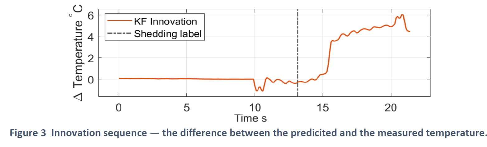
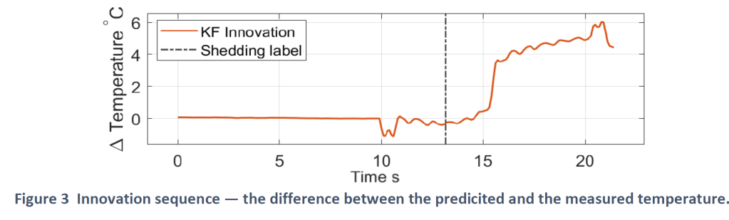
The ice shedding detection algorithm works by using two sources of information. The temperature sensors embedded in the wings and a model that relates the temperature measurements to the input from the heating panels. By comparing the expected temperature to the measured temperature, one obtains an error signal called the “innovation sequence.” The properties of the innovation sequence are such that it stays close to zero when the model and the measurements agree and grows large when they disagree. An example where the model and the measurements agree for the first 15 seconds is shown in Figure 3.
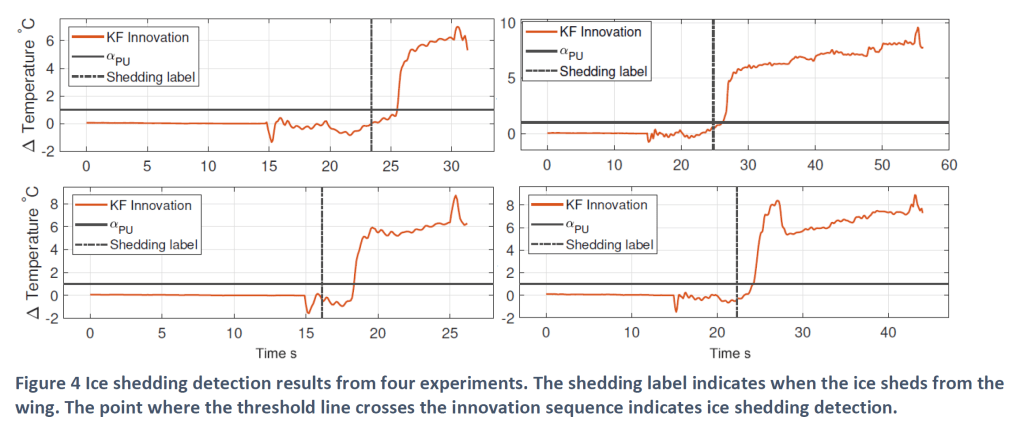
Now assume one has obtained a model of how the temperature in a UAV wing should behave when a layer of ice is surrounding it. With such a model, one can set up a detection threshold, based on the innovation sequence, to detect when the wing goes from being iced to being ice-free. By comparing data from several experiments, a threshold was found that could quickly and reliably identify ice shedding through the change of state in the wing from iced to ice-free. Figure 4 shows the four such detections in different de-icing experiments. The value αPU in the Figure 4 plots is the threshold at which the ice shedding detections are made.
The results show that ice shedding detection on a UAV is achievable. Furthermore, the average detection time of the presented method is only 2 seconds, allowing for efficient use of the IPS. The next step for the developed ice shedding detection system is to apply it in an actual flight, not only in an icing wind tunnel. Furthermore, it would be interesting to test the system together with an ice detection system which is supposed to initiate the de-icing process. To sum up, this research resulted in a method that can significantly reduce the energy requirements for UAV ice protection systems. By using this method in the future, UAVs will be able to operate safely and conduct longer missions inside icing conditions.
References
[1] Shakhatreh, H., Sawalmeh, A. H., Al-Fuqaha, A., Dou, Z., Almaita, E., Khalil, I., Othman, N. S., Khreishah, A., and Guizani, M., “Unmanned aerial vehicles (UAVs): A survey on civil applications and key research challenges,” IEEE Access, Vol. 7, 2019, pp. 48572–48634.
[2] Scalea, J. R., Restaino, S., Scassero, M., Blankenship, G., Bartlett, S. T., and Wereley, N., “An initial investigation of unmanned aircraft systems (UAS) and real-time organ status measurement for transporting human organs,” IEEE Journal of translational engineering in health and medicine, Vol. 6, 2018, pp. 1–7.
[3] Girard, A. R., Howell, A. S., and Hedrick, J. K., “Border patrol and surveillance missions using multiple unmanned air vehicles,” 2004 43rd IEEE conference on decision and control (CDC)(IEEE Cat. No. 04CH37601), Vol. 1, IEEE, 2004, pp. 620–625.
[4] M. Burgess, “Small drones are giving Ukraine an unprecedented edge,” Wired, 06-May-2022. [Online]. [Accessed: 10-May-2022].
[5] CNN, “Turkish drone is so effective, Ukrainian troops are singing about it,” YouTube, 07-Apr-2022. [Online]. Available: https://www.youtube.com/watch?v=S4qUsPCFV28. [Accessed: 18-May-2022].
[7] Hann, R., and Johansen, T. A., “UAV icing: the influence of airspeed and chord length on performance degradation,” Aircraft Engineering and Aerospace Technology, Vol. 93, 2021, pp. 832–841.
[8] Sørensen, K. L., Borup, K. T., Hann, R., Bernstein, B. C., and Hansbø, M., “Atmospheric icing limitations, climate report for Norway and surrounding regions,” Tech. rep., UBIQ Aerospace, 2021.
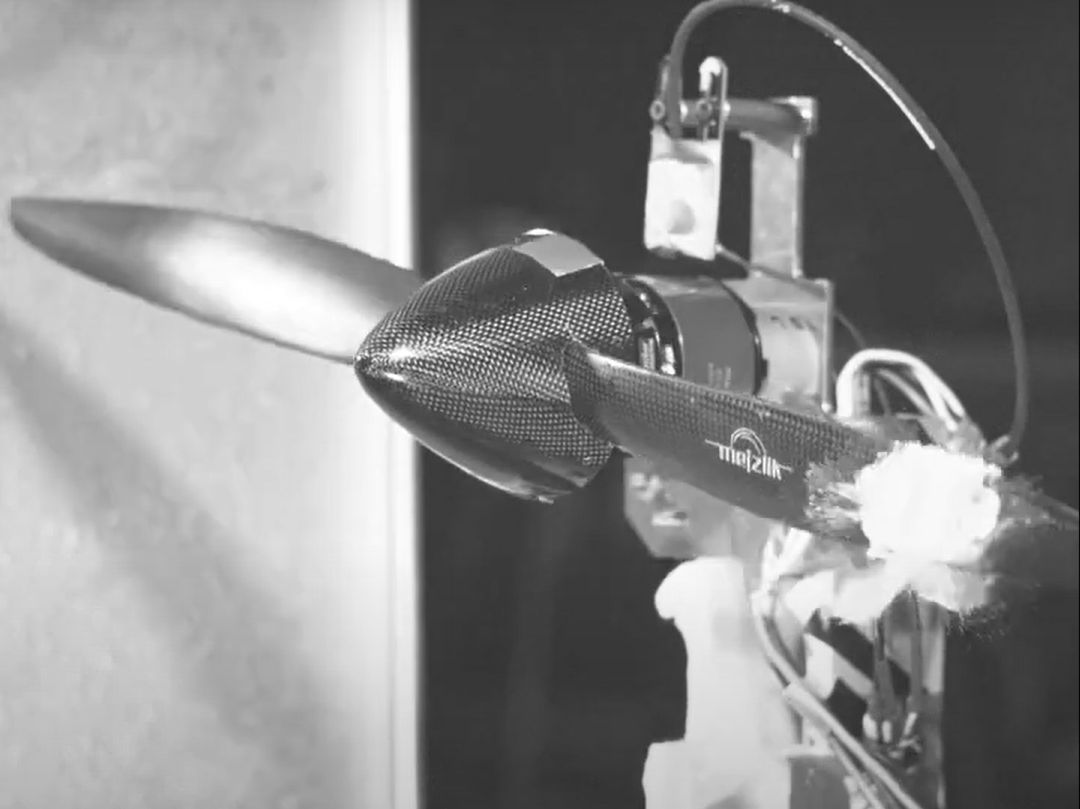
In one of our recent icing wind tunnel experiments, the NTNU UAV Icing Lab investigated if ice fragments are a hazard to UAV propellers. The resulting high-speed video footage shows the moment ice impacts the propeller blades. Here is a small preview of the footage.
When an aircraft flies into special meteorological weather conditions, ice can form on the airframe. When fragments of ice break off the surface, they can pose a hazard to the propeller. Such ice fragments can be created after long icing periods or in combination with de-icing systems. When an ice fragment hits the blades, there is a risk that the propeller might be damaged or destroyed – which may lead to the entire aircraft crashing. Especially for UAV propellers, which are often small and lightweight, this is a very relevant risk that can severely affect the safety of the drone.
The NTNU UAV Icing Lab is currently working together with UBIQ Aerospace and Mejzlik Propellers to study this topic. We are currently preparing a scientific paper about the issue.
The UAV Icing Lab has been featured in the online magazine NorwegianSciTechNews.com and its Norwegian counterpart, Gemini.no. The article is using a lot of multi-media elements and is aimed at the general public!
The Norwegian University of Science and Technology (NTNU) has signed a collaboration agreement with the German Aerospace Center (DLR). The scope of the agreement is to conduct joint research in the field of icing on unmanned aerial systems (UAVs). The collaboration is going to be pivoting around the NTNU UAV Icing Lab the the DLR Institute of Flight Systems
The DLR is the national aeronautics and space research centre of Germany. It has extensive research and development experience in aeronautic and other research fields. The DLR Institute of Flight Systems is part of several national and international projects and research cooperations to develop new high-quality simulation models as well as new ice detection methodologies. Profiting from its long tradition in aircraft model identification the Institute of Flight Systems has achieved outstanding results in the modelling of icing effects on manned aircraft during the last years.
Together with the NTNU UAV Icing Lab, the two partners will venture further into the field of icing on drones, with potential applications also for urban air mobility (UAM). The focus of the work will be to conduct model identification on iced unmanned aircraft provided by the UAV Lab. The DLR will contribute their experience in system identification and NTNU their operational experience and drones.