** NEW PUBLICATION ** The operation of unmanned aerial vehicles (UAVs) in icing conditions can be significantly limited because of aerodynamic performance penalties. For example, ice accretions on wings reduce lift and increase drag. The increased drag requires the aircraft to increase thrust, thereby increasing the required energy and limiting flight endurance and range.
Good mission planning and energy-efficient ice protection systems are required to maintain acceptable flight endurance and range. One piece of information that can help is the expected increase in drag under given icing conditions. Using this information, the expected reduction in flight endurance can be calculated, helping the operator to update his mission. Additionally, if the aircraft is equipped with a de-icing system, the drag prediction can help to control when to de-ice.
Existing drag predictions under icing conditions were based on manned aircraft Reynolds numbers and have not been extensively tested under UAV conditions. This new publication investigates the accuracy of existing correlations and proposes a new prediction of the increase in drag under icing conditions.
Method – To obtain as many data points as possible for comparison with existing correlations or for developing new predictions, numerical simulations were used. FENSAP-ICE simulations were run in a batch-automated way to reduce the manual setup time to setting up the baseline simulation and the condition matrix. The simulations predict ice growth under the selected conditions and the corresponding increases in drag. In total, 1798 data points were simulated.
Comparison with existing correlations – Each data point was compared to existing correlations. In general, all existing correlations showed the same phenomenon of a significantly wider range of predicted drag coefficients than the range of simulated drag coefficients, exemplarily shown here:
New prediction – Because of the bad fit of existing correlations with the simulation data, new correlations were developed that fit the simulated UAV case much better. Using separate equations for 3 different freezing fraction ranges, a correlation can be found that has a maximum deviation of only 23% from the simulated drag increases:
Summary – Predicting the increase in drag under given icing conditions can help operators optimize their in-flight mission planning. Existing correlations have been found to show bad agreement with a simulated UAV case. A new prediction has been developed that shows excellent agreement with the simulated data.
The numerical data require experimental validation, and the prediction method must be tested over a wider parameter range to verify its performance beyond the very specific case tested in this publication. Nevertheless, the good agreement between the new prediction and the simulation data indicates that this approach can be used to develop drag increase predictions for UAVs under icing conditions.
Reference: Wallisch, J.; Lindner, M.; Borup, K.T.; Hann, R. UAV Icing at Low Reynolds Numbers: RG-15 Airfoil Drag Increase Prediction Based on Batch-Automated CFD Simulations. J. Aerosp. Eng. 2026, 39, https://doi.org/10.1061/jaeeez.aseng-6806.
Doctoral candidate Joachim Wallisch at the Department of Engineering Cybernetics and NTNU UAV Icing Lab will hold a trial lecture and defend his doctoral thesis for the degree of philosophia Doctor (PhD.)
Thesis titleRecucing Energy Consumption of UAVs in Icing Conditions with Active Electrothermal De-Icing Protection Systems
Trial Lecture Related Challenges in Aviation: Surface Icing, Ice Shedding, and Contrail Formation
Time and venue
The PhD trial lecture and defence are both open to the public:
Trial lecture: 20 July 2026 at 10:15 – Disputasrommet, Main Building, Gløshaugen, NTNU
Defence of thesis: 20 July 2026 13:15 – Disputasrommet, Main Building, Gløshaugen, NTNU
You may also follow the defense online: Teams meeting
Assessment Committe
First opponent: Professor Serkan Özgen, Middle East Technical University
Second opponent: Assisant Professor Alyssa Avery, Oklahoma State University
Internal member: Professor Damiano Varagnolo, Department of Engineering Cybernetics
Professor Damiano Varagnolo, Department of Engineering Cybernetics NTNU, is appointed as the administrator of the assessment committee.
The committee has concluded that the thesis is worthy of public defense for the PhD degree.
Supervisors
Main supervisor: Dr Richard Hann
Co-supervisor: Professor Tor Arne Johansen
Dr Kasper Trolle Borup
Abstract
The operation of unmanned aerial vehicles (UAVs) can be limited by severe weather conditions, such as in-flight icing. Significant aerodynamic degradation can prevent operators from completing their flight missions or even starting them. Electrothermal de-icing ice protection systems are a popular method to mitigate the negative effects of ice accretion on wings. However, these systems require a lot of energy. This thesis investigated how electrothermal systems can be operated with reduced energy needs. This includes the heating energy required to remove ice from the surface and the increase in drag caused by ice growth while the system is idle. Reducing the required energy increases the aircraft’s range in icing conditions and can make UAV operation in these conditions viable.
Doctoral candidate Nicolas Carlo Müller at the Department of Engineering Cybernetics and UAV Icing Lab will hold a trial lecture and defend his doctoral thesis for the degree of philosophia Doctor (PhD.)
Thesis title: Ice accretion effects and ice protection systems for UAV propellers
Trial lecture: Pathways to Certifying UAVs for Icing Conditions: Technical Requirements (civil & defense), Means of Compliance, Certification by Simulation, and Remaining Gaps
Time and venue
The PhD trial lecture and defence are both open to the public:
Trial lecture: 15 July 2026 at 10:15 – Disputasrommet, Main Building, Gløshaugen, NTNU
Defence of thesis: 15 July 2026 13:15 – Disputasrommet, Main Building, Gløshaugen, NTNU
Assessment Committee
First opponent: Senior Scientist Mariachiara Gallia, Technische Universität Braunsweig
Second opponent: Associate Professor Reinhardt Puffing, FH Joanneum University of Applied Sciences
Internal member: Associate Professor Dinesh Krishnamoorthy Kallur, Department of Engineering Cybernetics. He is also is appointed as the administrator of the assessment committee.
The committee has concluded that the thesis is worthy of public defense for the PhD degree.
Supervisors
Main supervisor: Dr Richard Hann
Co-supervisor: Professor Tor Arne Johansen
Abstract
As unmanned aerial vehicles (UAVs) increasingly support critical missions in cold climates, atmospheric icing poses a severe threat to their operational safety. This dissertation presents a numerical and experimental analysis of UAV rotor icing and introduces novel mitigation strategies to ensure reliable all-weather flight. Utilizing a hybrid approach that combines icing wind tunnel experiments with high-fidelity computational fluid dynamics (CFD) modeling, this research characterizes the complex thermodynamics of ice accretion on small-scale rotating blades. The study quantifies the aerodynamic penalties, including thrust degradation and power increases, caused by various icing conditions. To address these vulnerabilities, the thesis proposes and evaluates a electro-thermal anti-icing system. Evaluation of the system in an icing wind tunnel demonstrates the ability to reduce the performance penalties from ice accretion on the propeller and minimize the power consumption of the system. This work provides a key step to enable UAVs to operate in adverse weather conditions by maintaining the propulsion capabilities of the UAV.
Doctoral candidate Bogdan Løw-Hansen at the Department of Engineering Cybernetics and the UAV Icing Lab will hold a trial lecture and defend his doctoral thesis for the degree of philosophia Doctor (PhD.)
Thesis titleModelling and validation of atmospheric icing effects on small fixed-wing UAV’s
Trial Lecture Optimal Excitation Maneuvers for UAV System Identificatoin in Closed Loop Flight
Time and venue
The PhD trial lecture and defence are both open to the public:
Trial lecture: 13 July 2026 at 12:15 – Disputasrommet, Main Building, Gløshaugen, NTNU
Defence of thesis: 13 July 2026 at 14:45– Disputasrommet, Main Building, Gløshaugen, NTNU
Assessment Committee
First opponent: Assistant Professor Sofie F. Armanini, Imperial College London
Second opponent: Research Aerospace Engineer Benjamin M. Simmons, NASA Langley Research Center
Internal member: Professor Ole Morten Aamo, Department of Engineering Cybernetics. He is also appointed as the administrator of the assessment committee.
The committee has concluded that the thesis is worthy of public defense for the PhD degree.
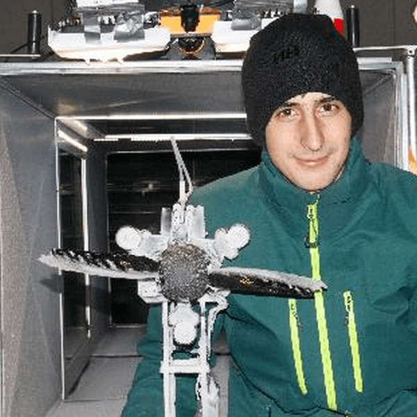
**NEW PUBLICATION** In one of our recent icing wind tunnel campaigns, the NTNU UAV Icing Lab investigated how ice accretion affects the performance of a UAV propeller in collaboration with Ubiq Aerospace and the Université du Québec à Chicoutimii (UQAC). What happens when a drone rotors are exposed to icing conditions and start to develop irregular ice shapes?
The answer: performance can collapse in less than a minute.
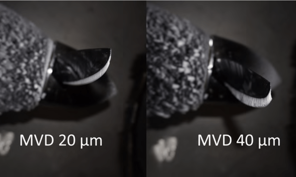
In controlled icing conditions in the icing wind tunnel facilities of the UQAC Anti-Icing Materials International Laboratory, we exposed a 53 cm-diameter carbon-fiber propeller to different temperatures, droplet sizes, and liquid water contents. While ice mass certainly increased with harsher conditions, the most important factor was not how much ice formed — but how it formed.
Small droplets produced relatively smooth, streamlined ice shapes with moderate performance loss. Larger droplets created rough, horn-like ice structures. These disrupted the airflow so severely that thrust dropped to zero — and in the worst cases, the propeller began generating drag instead of thrust.
For small UAVs operating close to their performance limits, this is critical. A rapid thrust loss combined with increased power demand can quickly lead to loss of control.
Our results show that droplet size and temperature strongly influence ice shape — and therefore risk. Understanding these mechanisms is essential for designing effective ice protection systems and enabling reliable UAV operations in cold climates.
We are currently working on improved modeling and mitigation strategies to better predict and manage these icing effects.
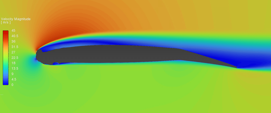
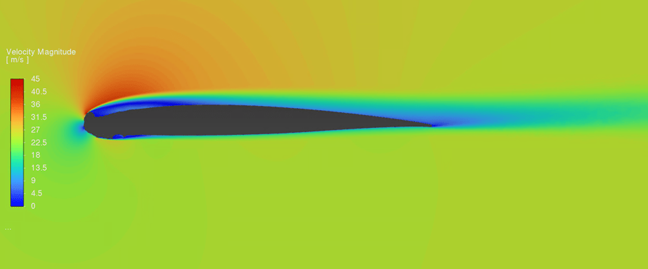
The adverse effects of in-flight icing on small fixed-wing UAVs are a research topic with increasing interest. While the research primarily focuses on clean wing configurations, the impact of leading-edge ice accretion on the aerodynamic performance with deflected control surfaces has been neglected. However, ice accretion has a significant effect on the flow field downstream.
Comparison of the flow fields at 4° AOA with glaze ice accretion at 0° and 10° control surface deflection.
Modeling Iced Airfoils with Deflected Control Surfaces
In previous icing wind tunnel campaigns, experimental ice shapes were accreted using an RG-15 airfoil with 30 cm chord length. The temperatures during the ice accretion process have an influence on the shape of the resulting ice. Typically, three different ice types are distinguished: rime, mixed, and glaze ice, with rime being the coldest. In this set-up, these ice types were achieved at –10, –4, and -2 °C, respectively, at an airspeed of 25 m/s and a liquid water content of 0.52 g/m^3. After an ice accretion time of 20 min, the ice shapes were digitized and the maximum combined cross-section (MCCS) calculated.
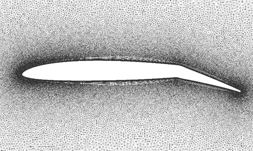
Since the actual investigation is done using computational fluid dynamics (CFD) simulations, the MCCSs of the ice shapes are attached to the leading edge of an RG-15 airfoil in a meshing software. The control surface, which in this context can be an aileron or flap, is represented by a deflection of the airfoil starting at 70% chord-wise position. The goal of this study is to see the change in aerodynamic performance of an airfoil at different control surface deflections with and without ice accretion. This study compares five deflection angles, -5 °, 0°, 5°, 10°, and 15° (downward deflection positive), for the three ice shapes and the un-iced wing. It is especially of interest to see how a deflection of the control surface changes the lift, drag, and generated moments, and how this is affected by icing.
Simulation grid with control surface deflection
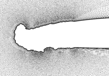
Details of the grid with glaze leading-edge ice.
The Combined Effect of Ice and Deflected Control Surfaces on Lift
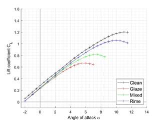
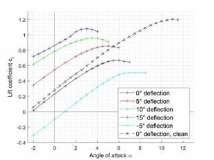
The (positive) deflection of a control surface on an un-iced airfoil increases lift coefficient and decreases the stall angle. Leading-edge ice accretion decreases both the lift coefficient and the stall angle. Combining both effects can result in hazardous flight situations. Looking at glaze ice as the most severe ice shape in terms of aerodynamic performance degradation, this effect becomes apparent. The undeflected case already shows a significant reduction in max. lift coefficient compared to the un-iced case. Deflecting the control surface shows the expected effect of increased lift; however, in a significantly reduced magnitude, not reaching the un-iced max. lift even at a 15° deflection angle. The results for the rime and mixed ice cases can be found in the corresponding publication.
Lift coefficient for 0° control surface deflection.
Lift at different control surface deflections with glaze ice accumulation.
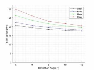
The reduction of the stall angle and thereby the max. lift coefficient has implications on the stall speed, i.e., the min. required velocity to be able to maintain horizontal flight at the stall angle. In all iced cases, this velocity is increased, most severely for glaze. The higher velocity of the UAV produces more drag, which the thrust of the propeller must match. However, the drag coefficient is also impacted by the deflection of the control surface.
Comparison of stall speeds for different control surface deflection angles and ice types.
What about the Drag?
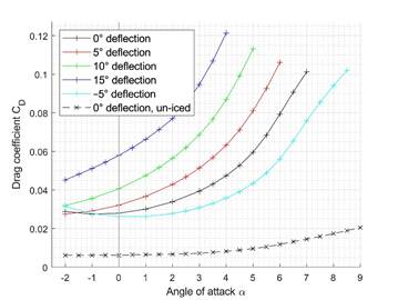
The drag coefficient paints an even worse picture than the lift coefficient. Again, comparing the results of the glaze ice cases, already the ice accretion increases the drag coefficient by 480% at an angle of attack of 4°. Deflecting the control surface, the drag coefficient increases by 450%, 440%, 330%, and 190% for −5°, 5°, 10°, and 15°, respectively, compared to the corresponding un-iced deflection angles. In combination with the higher flight velocity or higher angle of attack, the thrust that the propeller can provide (given it is protected against ice accretion) might reach its limit. Nevertheless, this depends on the individual UAV and the propeller.
Drag coefficient of the clear wing and for the glaze ice shape.
Longitudinal Stability and Control of Iced Airfoils
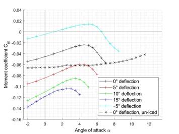
A third part of this investigation focuses on the impact on longitudinal stability and controllability of iced UAV wings. To evaluate the longitudinal stability of an airfoil against disturbances, the gradient of the curve is significant. A negative gradient indicates a statically stable behaviour, meaning the airfoil creates a moment to return to the initial flight attitude after a disturbance. While the un-iced pitching moment coefficient curve have mostly a negative gradient, all iced simulations feature a significantly greater positive gradient, revealing considerably more unstable behaviour. The curves of the pitching moment for the glaze ice cases can be found in the picture below.
Moment Coefficient at different control
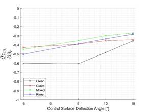
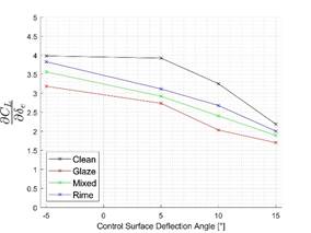
The longitudinal control derivative 𝐶𝑚𝛿eis defined as the change in moment when deflecting the control surface. This can be used in a simulator to study the flight behavior of an iced UAV. The figure below displays the control derivatives 𝐶𝑚𝛿e for the un-iced wing and with leading-edge ice accretion of three ice types for an angle of attack of 4°. Two aspects can be observed: First, the control surface effectiveness is reduced in comparison with the un-iced case. This means that, with the same deflection, less moment is generated, requiring greater deflection of the control surfaces, with all the downsides discussed earlier: reduced stall margins and increased drag. Secondly, while the change in moments generated when deflecting upward and downward is the same in the un-iced case, this no longer applies in the iced cases, leading potentially to unexpected behaviour when the control surfaces are used as ailerons and are deflected in opposite directions.
Change of 𝐶_𝑚𝛿𝑒 in iced conditions
Change of 𝐶_𝐿𝛿𝑒 in iced conditions
Summary
Leading-edge ice accretion has a severe impact on the aerodynamic performance of a small fixed-wing UAV. When downstream of the ice accretion a control surface is deflected, the adverse effects are amplified, potentially causing hazardous flight conditions that can lead to the loss of the aircraft. The deflection of the control surfaces further reduces stall margin, increases drag, and reduces the control surface effectiveness. This further stresses the need for mitigation strategies against in-flight icing, methods to reliably detect icing conditions, and methods to estimate the UAV’s aerodynamic state.
I’m looking forward to speaking at UNC 2026, a key Nordic industry event bringing together UAV operators, regulators, and technology developers. The conferene is 9-10 Febuary in Oslo, Norway.
Icing remains one of the most underestimated risks in UAV operations across the Nordics, often grounding missions far beyond Arctic regions. Even small amounts of ice can severely affect aerodynamics, sensors, and autonomy – making icing a major barrier to reliable year-round BVLOS operations.
In this session, I’ll discuss how new ice-detection and mitigation technologies can help overcome this barrier and enable safer, more robust UAV operations in cold climates. The focus will be on practical solutions that move icing from a hard operational stop toward a manageable risk.
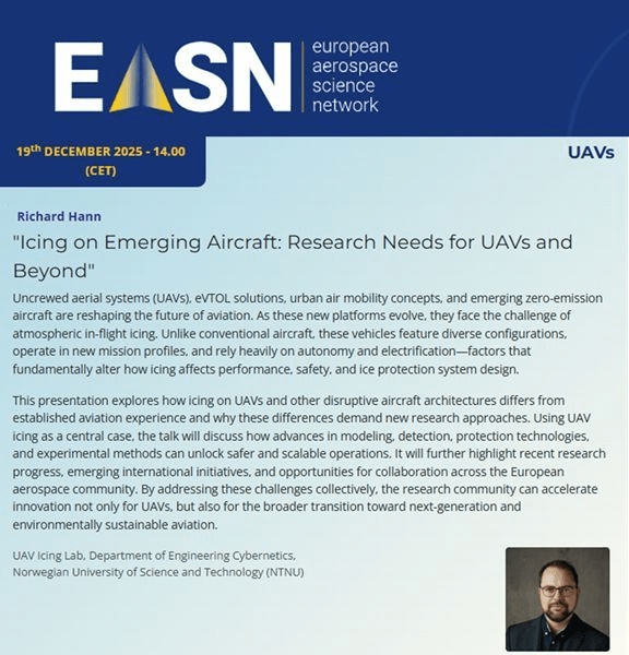
I’m very honoured to be invited to speak about this at the European Aerospace Science Network (EASN) research webinar on 19th December at 14:00 CET. In my talk titled “Icing on Emerging Aircraft: Research Needs for UAVs and Beyond”, I’ll introduce why icing remains such a pressing challenge for unmanned and disruptive aircraft—and why the solutions we need must be reframed entirely for these new classes of vehicles. Tune in for a free online webinar just before the holiday break! (Link: https://lnkd.in/eWb49vag)
Why this topic matters
Unlike large airliners, UAVs and many emerging aircraft have:
Very tight power, weight, and size constraints, making traditional ice protection systems often unfeasible.
High sensitivity to even small amounts of ice, since ice accretion alters aerodynamic performance dramatically—reducing lift, increasing drag, and degrading control effectiveness.
A growing range of operational missions, from scientific data collection in Arctic regions to beyond-visual-line-of-sight commercial flights, where icing risk cannot simply be avoided.
Our recent work at the UAV Icing Lab has shown the deep influence of icing on UAV performance and the need for new modelling, detection, mitigation, and protection approaches tailored to these platforms. From optimized electro-thermal ice protection systems for propellers to assessments of aerodynamic penalties and the emerging integration of mission planning with icing risk indices, this field is rapidly evolving to support the next generation of operations.
Key themes in the talk
In the webinar I’ll discuss:
Fundamental differences between icing effects on conventional aircraft and on UAVs or disruptive configurations.
Why autonomy and electrification change the game for icing research, including how sensing, control, and power budgets interact with icing challenges.
Advances in modelling and experimental methods that unlock safer and more scalable solutions.
Recent research highlights and emerging collaboration opportunities across the European aerospace community to accelerate innovation—not only for UAVs but for the broader transition toward next-generation, environmentally sustainable aviation.
Looking forward
This talk is both a summary of where the field stands and a call to the aerospace research community: as we push aircraft into new domains of autonomy, sustainability, and performance, we must not overlook the atmospheric hazards that accompany these innovations. In-flight icing is one such hazard where tailored research and multidisciplinary solutions will be critical for the future of unmanned and disruptive aircraft alike.
I’m incredibly honoured to be invited to speak at the upcoming Aircraft Icing Forum, a recurring monthly forum that brings together experts from research, industry, and regulatory bodies to discuss aircraft icing technologies, certification, and operational challenges – hosted by the FAA and NASA.
The Aircraft Icing Forum plays a unique role in the icing community by providing a continuous space for open technical exchange—something that is increasingly important as aviation expands into new operational domains. I’m grateful for the opportunity to contribute to these discussions with a focus on UAVs and emerging aircraft concepts.
Why “new frontiers” of aircraft icing?
Unmanned aerial systems (UAVs), eVTOL platforms, urban air mobility concepts, and zero-emission aircraft are rapidly expanding aviation into a new future. Along with new capabilities and mission profiles, these aircraft introduce a new frontier of icing challenges.
Unlike conventional aircraft, many emerging platforms:
Operate with very limited power and mass margins,
Rely heavily on electrification and autonomy,
Feature non-traditional configurations (distributed propulsion, small propellers, novel airframes), and
Fly in operational environments where icing exposure cannot always be avoided.
These factors fundamentally change how icing affects performance, safety, and system design—and they demand new technical solutions rather than direct adaptations of legacy approaches.
What I’ll cover in the talk
My presentation, titled “New Frontiers of Aircraft Icing: UAVs and Beyond”, will provide a broad introduction to how icing manifests on UAVs, eVTOLs, and emerging aircraft, and why established icing paradigms must be re-examined for these platforms.
Using UAV icing as a central example, the talk will highlight:
How icing physics, aerodynamics, and system impacts differ for small, electrically powered, and highly autonomous aircraft
Why new modelling, detection, and protection technologies are required to meet safety and operational needs
Recent advances in UAV icing research, including experimental methods and system-level approaches
Ongoing international initiatives and key open questions that must be addressed to enable safe and scalable operations across this rapidly evolving landscape
The goal is not only to share recent progress, but also to stimulate discussion around where the community should focus next, particularly at the intersection of technology development, certification, and operations.
** NEW PUBLICATION ** Operating drones in cold weather causes multiple challenges. Atmospheric in-cloud icing is one of them. Aircraft are often grounded during potential icing conditions because of significant performance degradation caused by ice accretion. Ice protection systems (IPS) are one way to mitigate icing-induced performance degradations and to open the atmospheric flight envelope. However, IPS do not necessarily prevent performance degradations completely. For this study, we looked at potential performance degradations that can occur even when operating an electrothermal de-icing system on a UAV wing. Electrothermal describes that the aircraft skin is heated using electrical energy. De-icing systems allow some ice accretion before removing the ice, contrary to anti-icing systems that prevent any ice accretion.
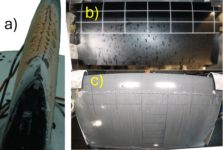
Setup – Two common types of ice accretion with a thermal de-icing system are intercycle and runback icing. Intercycle ice is the accretion that grows before the system is activated to remove the ice. An example of an intercycle ice shape after four minutes is shown below. Runback ice typically grows downstream of the heated areas. When the wing is heated, some of the meltwater will flow downstream and re-freeze in unheated areas. Runback ice can occur as dispersed spots of ice or as spanwise ice ridges.
Different ice shapes: a) An intercycle ice shape after 4 minutes; b) Dispersed runback ice; c) A spanwise ice ridge.
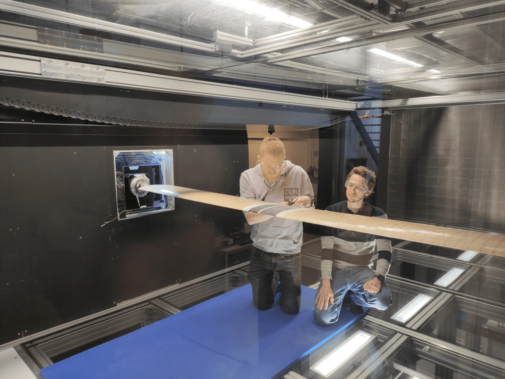
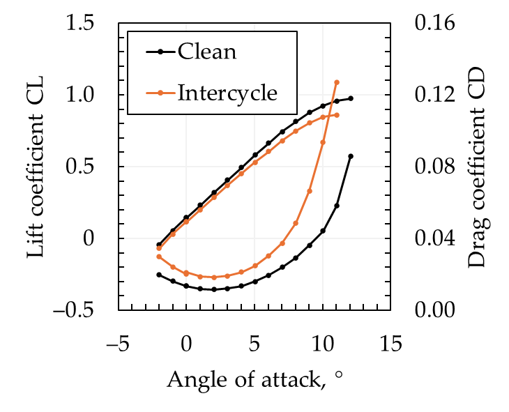
Our study investigated the changes in lift coefficient, drag coefficient, and stall angle caused by ice accretions. Experimental wind tunnel tests and numerical simulations were conducted. The wind tunnel tests were performed at the low-speed wind tunnel at NTNU. An RG-15 wing with a chord length of 0.3 m and 2.65 m span was tested at 10 m/s. Numerical simulations were conducted with Ansys FENSAP-ICE, a state-of-the-art icing simulation tool.
Results– The intercycle ice shape results in a degraded aerodynamic performance compared to the clean wing. At the realistic cruise angle of attack of 4°, the drag is increased by 58%, and the lift coefficient is reduced by 9%. This means that the aircraft would have to increase its thrust by 58% to continue its flight when flying with the intercycle ice shape compared to a clean aircraft.
The aerodynamic influence of runback ice depends significantly on the type of ice that grows. Dispersed runback ice spots reduce the lift coefficient by 2% and increase the drag coefficient by 32% compared to the clean wing at 4° angle of attack. A spanwise ice ridge reduces the aerodynamic performance more significantly. The drag coefficient at 4° angle of attack is increased by 177%, while the lift coefficient is 16% lower than in the clean case. If the UAV is intended to continue its flight in icing conditions, it would need almost three times as much thrust with the spanwise ice ridge than without. This is particularly significant because the ice ridge will likely grow in an unprotected area. Hence, the only way to remove the spanwise ice ridge would be to fly into areas with a temperature above freezing long enough to melt the ice.
Summary – Knowing the performance degradation in icing conditions is important for manufacturers and operators of UAVs and IPS. Because drones do not have much electric energy available, energy efficiency is key. This study showed that:
Spanwise ice ridges must be prevented because of the large drag increase and because they grow in unprotected areas.
Intercycle ice and runback ice cause non-negligible drag increases and must be considered when calculating the required energy of a thermal de-icing system.
Because runback ice grows in unprotected areas, removing it is difficult. Hence, avoidance strategies must be developed instead. Strategies to reduce the amount of runback ice include special coatings, less frequent de-icing, and adjusted heating layouts and sequences.